Note: The idlers and motor pulleys are mounted different on each side.
Jointer Pins/Idlers Left Side
- Install (2) "5x30mm Round Pins" in the "Jointer Left Bottom"
- Place 1 "Toothed Idler" on the front facing side of the "Jointer Left Bottom" (Side facing the front of the printer).
- Place 1 "Smooth Idler" on the back facing side of the "Jointer Left Bottom" (Side facing the back of the printer).
Jointer Pins/Idlers Right Side
- Install (2) "5x30mm Round Pins" in the "Jointer Right Bottom"
- Place (1) "Toothed Idler" on the front facing side of the "Jointer Right Bottom" (Side facing the front of the printer).
- Place (1) "Smooth Idler" on the back facing side of the "Jointer Right Bottom" (Side facing the back of the printer).
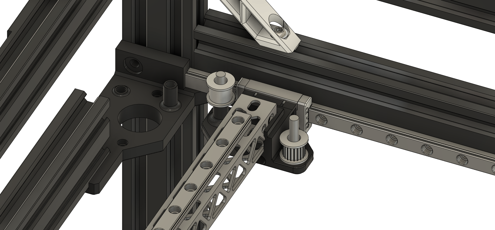
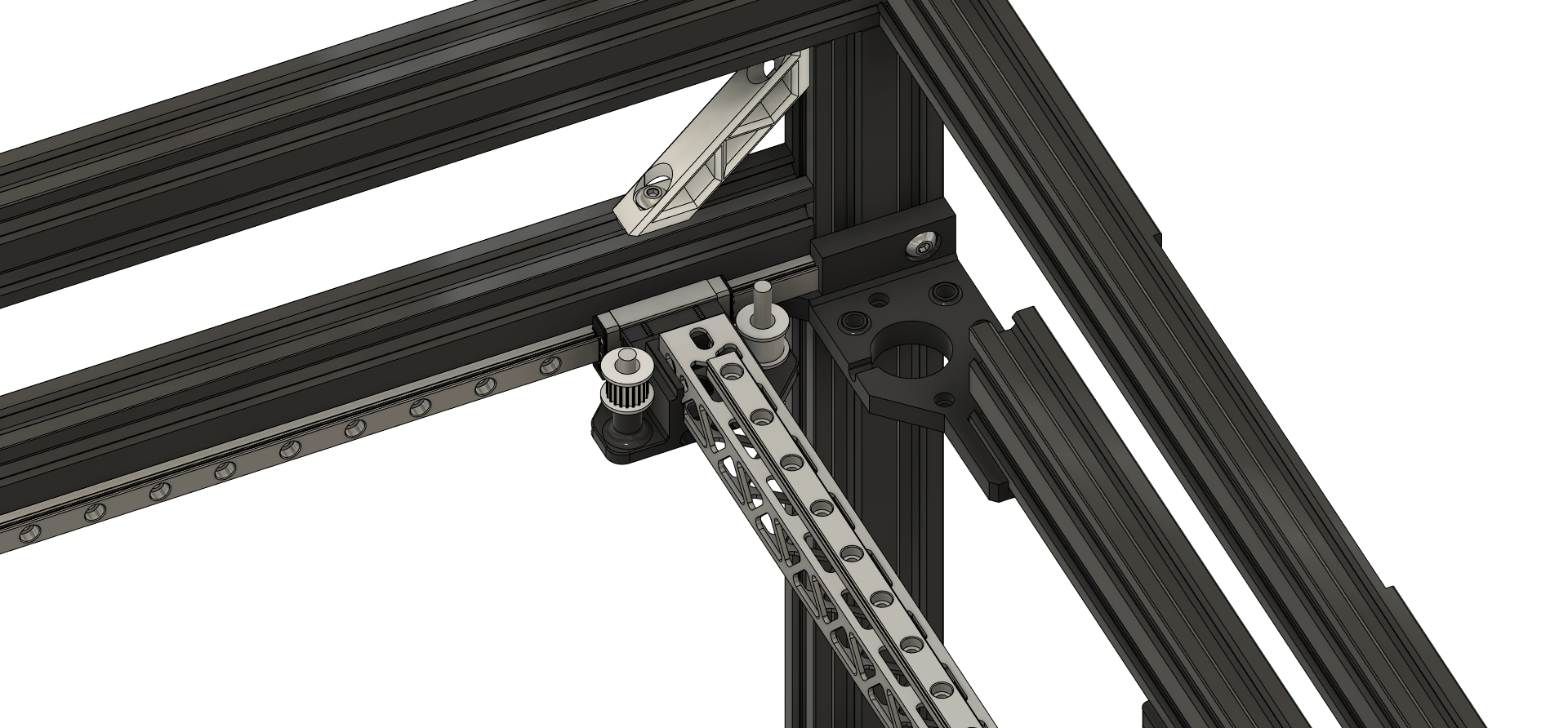
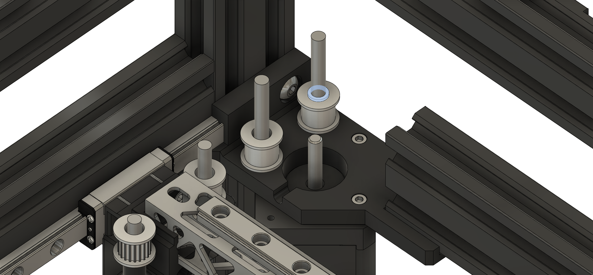
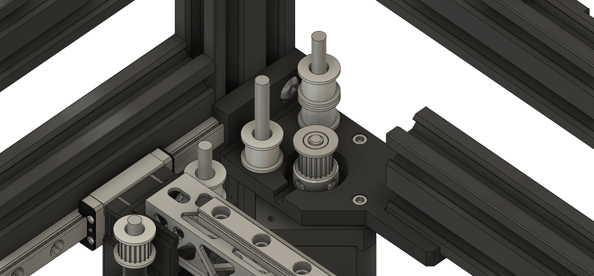
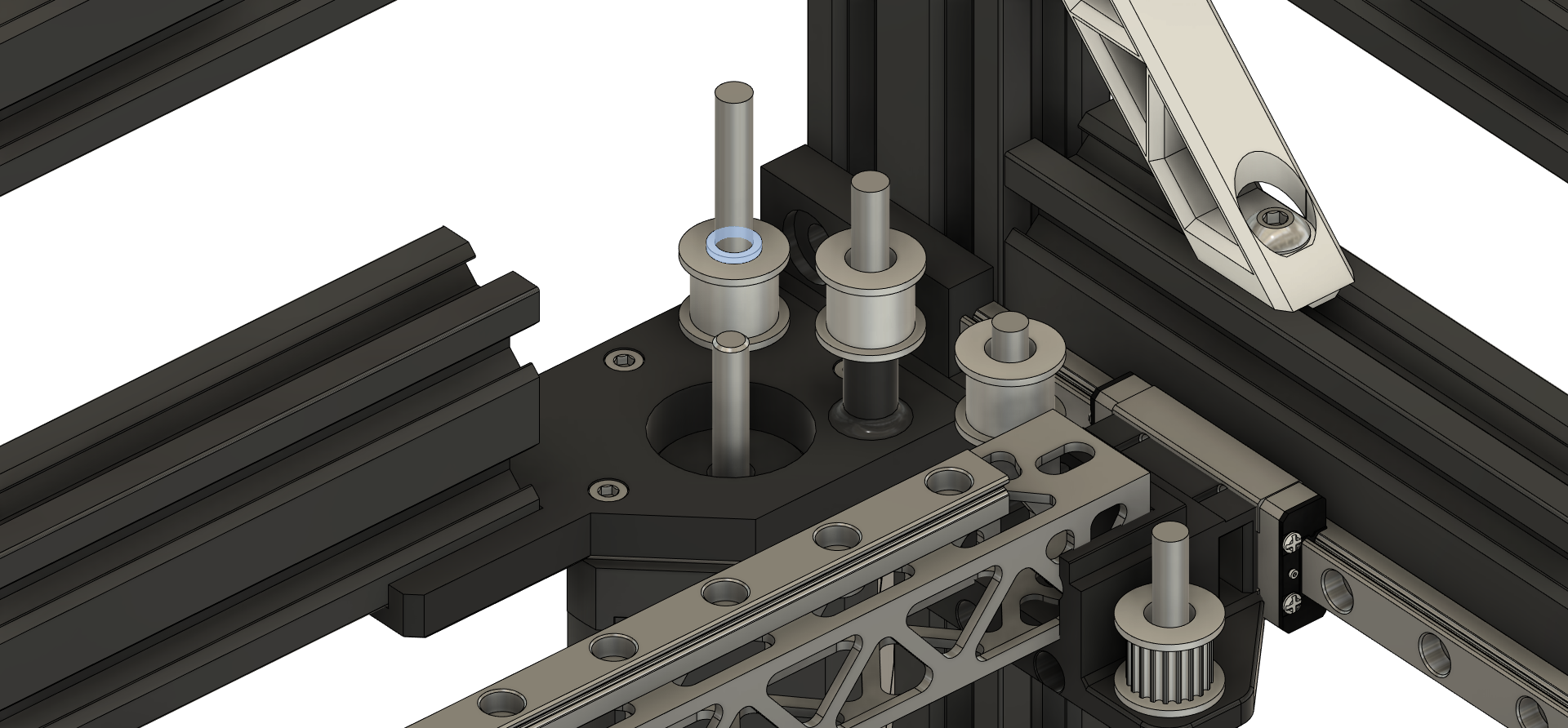
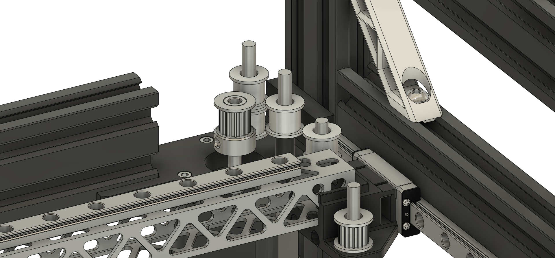
Motor Pins/Idlers/Pulley Left Side
- Install (2) "5x40mm Round Pins" in the "B Drive Lower Left" Motor mount.
- Place (1) "Smooth Idler" on the back facing side of the "B Drive Lower Left" Motor mount with a "1mm Spacer". (Side facing the back of the printer).
- Place (1) "Smooth Idler" on the front facing side of the "B Drive Lower Left" Motor mount (Side facing the front of the printer).
- Now place (1) more "Smooth Idler" on the back facing side of the "B Drive Lower Left" Motor mount with the other and place the "Motor Pulley" on motor. Adjust so that it lines up with the "Bottom Idlers".
Motor Pins/Idlers/Pulley Right Side
- Install (2) "5x40mm Round Pins" in the "A Drive Lower Right" Motor mount.
- Place (1) "Smooth Idler" on the back facing side of the "A Drive Lower Right" Motor mount with a "1mm Spacer". (Side facing the back of the printer).
- Place (1) "Smooth Idler" on the front facing side of the "A Drive Lower Right" Motor mount (Side facing the front of the printer).
- Now place (1) more "Smooth Idler" on the back facing side of the "A Drive Lower Right" Motor mount with the other and place the "Motor Pulley" on motor. Adjust so that it lines up with the "Top Idlers".
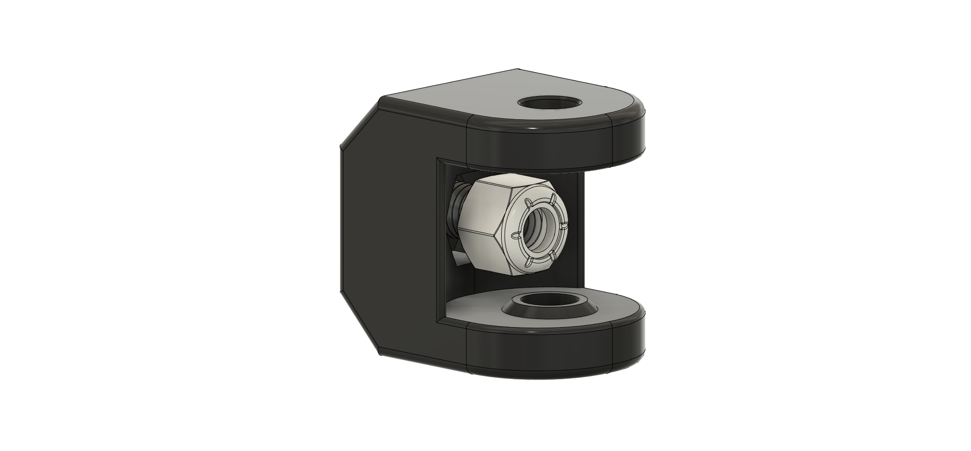
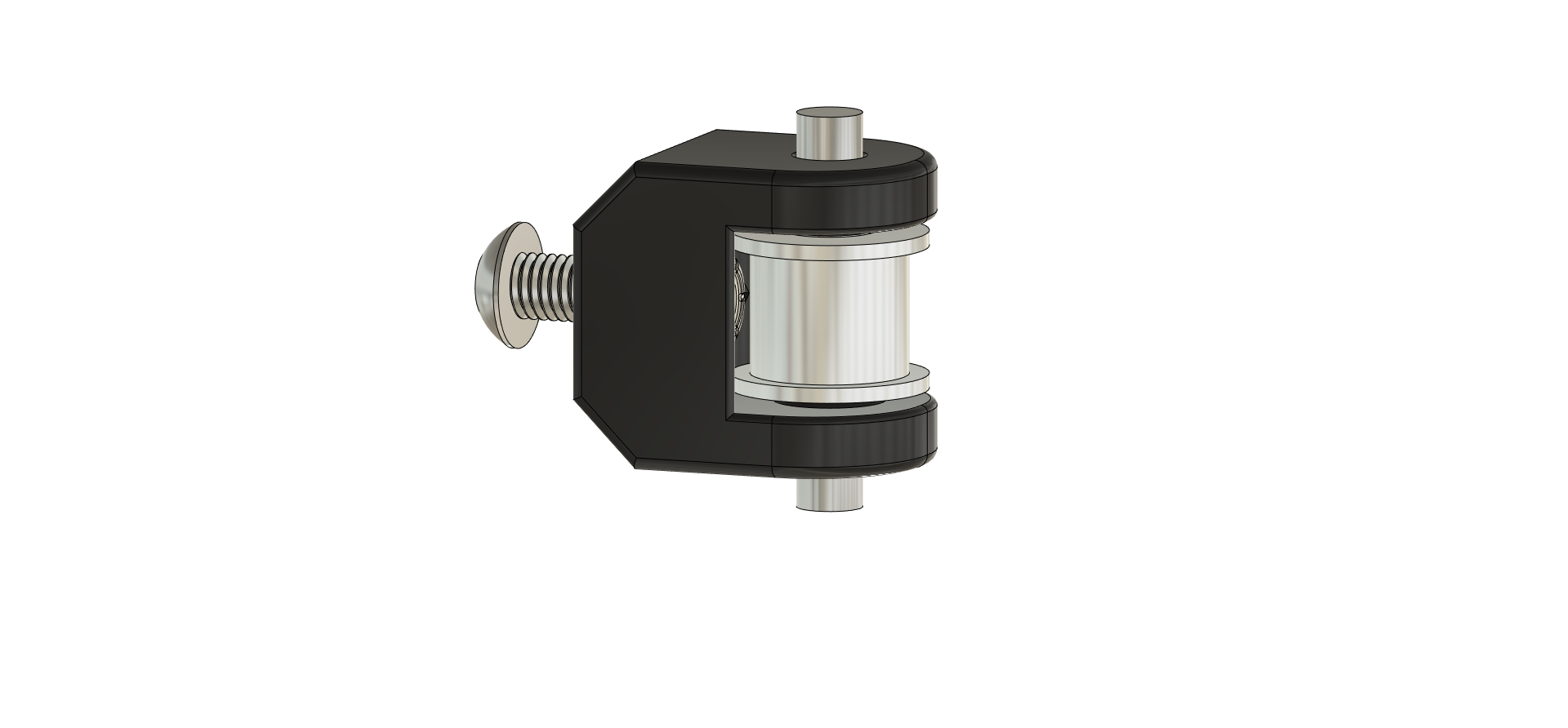
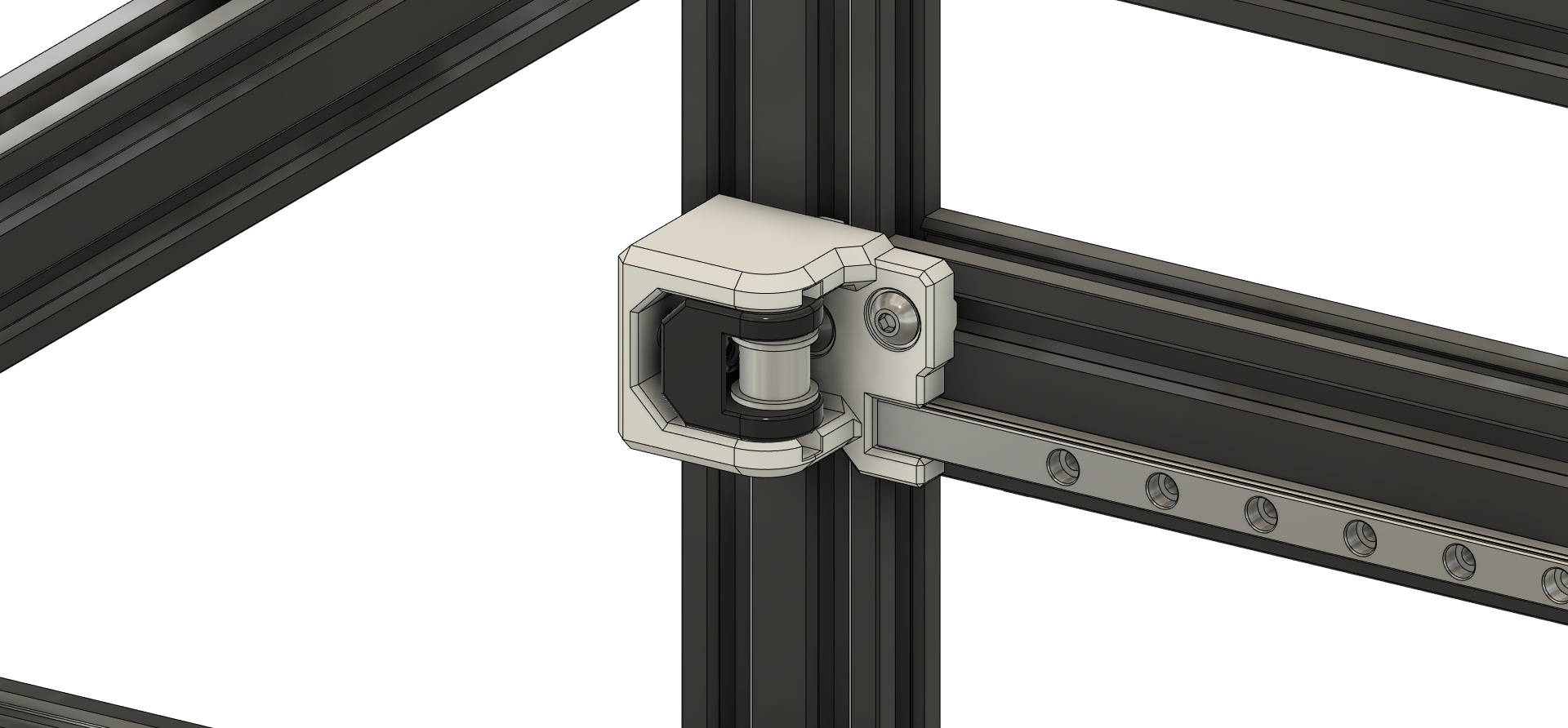
Front Idler Blocks
Note: The Inside Front Idler Block is the same for both sides.
- Run the M5x12mm screw for the "Front Idler Adjustment" though the front hole, now put a M5 lock nut on the screw and pull it into the recessed cutout for the Nut.
- Slide (1) "Smooth Idler into the Block and push the "5x30mm Round Pin" thought till there is about the same amount of Pin on both sides.
- Now you can remove the M5x12mm screw and slide the assembled "Front Idler Block" into the "Front Idler Mount" and thread the screw 1-2 turns by hand to help hold it in place.